Version 1.0
This document specifies the requirements for headsets and mobile devices to function uniformly across the Android ecosystem. It is separated into two sections beginning with the specifications for the headset accessory followed by the specifications for the mobile device.
The requirements in the following section apply to the headset accessory.
|
Function |
Accessory Support |
|---|---|
|
Stereo Audio Out |
Required |
|
Audio in (Mic) |
Required |
|
Ground |
Required |
|
Control Function |
Accessory Support |
Description |
|---|---|---|
|
Function A |
Required |
Play/pause/hook (Short Press), Trigger Assist (Long Press), Next (double press) |
|
Function B |
Optional |
Vol+ |
|
Function C |
Optional |
Vol- |
|
Function D |
Optional |
Reserved (Nexus devices will use this reserved function to launch Google Now voice search) |
Assign functions to buttons as follows:
|
Function |
Accessory Support |
Notes |
|---|---|---|
|
4 conductor 3.5mm plug |
Required |
Ref: EIAJ-RC5325A standard |
|
CTIA pinout order (LRGM) |
Required |
Except in regions with legal requirements for OMTP pinout |
|
OMTP pinout order (LRMG) |
Optional |
|
|
Microphone |
Required |
Must not be obstructed when operating headset controls |
|
Function |
Accessory Support |
Description |
|---|---|---|
|
Ear speaker impedance |
16 ohms or higher |
Recommend 32 - 300 ohms |
|
Mic DC resistance |
1000 ohms or higher |
Mic characteristics must be compliant with section 5.4 “Audio Recording” of current Android Compatibility Definition Document (CDD) |
|
Control Function Equivalent impedance* *Total impedance from positive mic terminal to GND when button is pressed with 2.2 V mic bias applied through 2.2 kOhm resistor |
0 ohm |
[Function A] Play/Pause/Hook |
|
240 ohm +/- 1% resistance |
[Function B] |
|
|
470 ohm +/- 1% resistance |
[Function C] |
|
|
135 ohm +/- 1% resistance |
[Function D] |
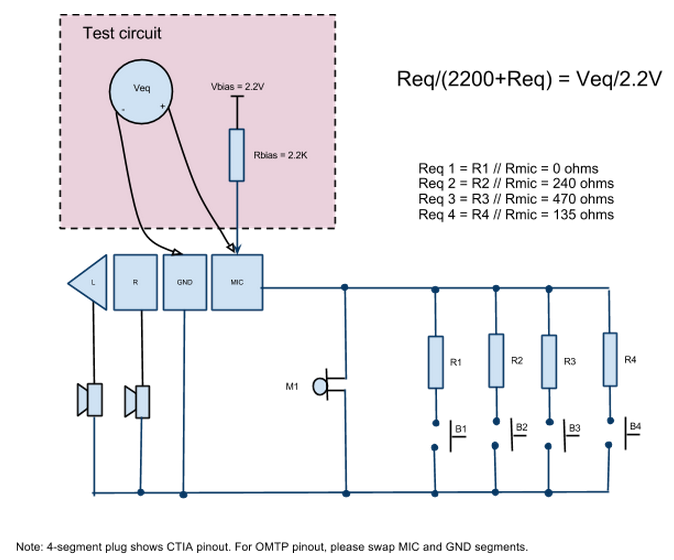
Figure 1. Reference headset test circuit 1
Note: Four-segment plug shows CTIA pinout. For OMTP pinout, please swap MIC and GND segments.
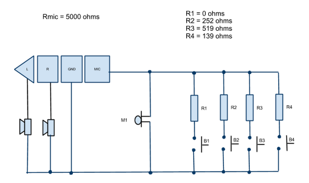
Figure 2. Reference headset test circuit 2
Note: The second reference circuit above illustrates how the actual resistor values (R1 - R4) will change based on the microphone capsule resistance to achieve the equivalent impedance values as required by the specification. The example above assumes a 5 kOhm microphone impedance. Therefore, as an example, to achieve an equivalent R4 impedance of 135 Ohm, the actual R4 resistor value needs to be 139 Ohms.
Caution: To achieve compatibility with the headset specification above, devices that include a 4 conductor 3.5mm audio jack must meet the following specifications. Please see the Analog audio ports section of the Android Compatibility Definition Document (CDD) for Android compatibility requirements.
Headset Jack Functions
|
Function |
Device Support |
|---|---|
|
Stereo Audio Out |
Required |
|
Audio in (Mic) |
Required |
|
Ground |
Required |
|
Function |
Device Support |
Description |
|---|---|---|
|
Function A control event |
Required |
input event KEY_MEDIA Android key KEYCODE_HEADSETHOOK |
|
Function D control event |
Required |
input event KEY_VOICECOMMAND Android key KEYCODE_VOICE_ASSIST |
|
Function B control event |
Required |
input event KEY_VOLUMEUP Android key VOLUME_UP |
|
Function C control event |
Required |
input event KEY_VOLUMEDOWN Android key VOLUME_DOWN |
|
Headset insertion detection |
Required |
input event SW_JACK_PHYSICAL_INSERT 7 |
|
Headset type detection |
Mic |
input event SW_MICROPHONE_INSERT 4 |
|
Headset type detection |
No Mic |
input event SW_HEADPHONE_INSERT 2 |
|
Headset speaker impedance |
Required Headphone (low) |
Failure mode is to indicate headphones so that limitation would be on |
|
Headset speaker impedance |
Required Line In (high) |
input event SW_LINEOUT_INSERT 6 |
|
Function |
Device Support |
Description |
|---|---|---|
|
4 conductor 3.5mm jack |
Required |
|
|
CTIA pinout order (LRGM) |
Required |
3 Pin & Mono Plug Compatible |
|
OMTP pinout order (LRMG) |
Optional but Strongly Recommended |
|
|
Headset detect sequence |
Required |
Plug insert notification must only be triggered after all contacts on plug are touching their relevant segments. This will prevent unreliable headset detection due to slow insertion. |
|
Function |
Device Support |
Notes |
|---|---|---|
|
Minimum output voltage drive capacity |
150mV |
>= 150mV on 32 ohm Test conditions: EN50332-2 |
|
Mic bias resistance |
Required |
Flexible on detection method used and microphone bias resistor selection. Require that all button resistance value ranges specified below be detected and related to their respective function |
|
Mic bias voltage |
1.8V - 2.9V |
To guarantee compatibility to common microphone capsules. |
Devices must detect the following resistor ladder on the accessories. The accessories will be tested to the standardized circuit diagram in the diagram illustrated earlier (Reference Headset Test Circuit) where the total impedance is measured from MIC terminal to GND when a button is pressed with 2.2V mic bias applied through 2.2 kOhm resistor. This is the same effective resistance as the button detection circuit with the microphone in parallel with the button resistor.
|
Button Impedance Level |
Device Support |
Notes |
|---|---|---|
|
70 ohm or less |
Required |
[Function A] |
|
110 - 180 ohm |
Required |
[Function D] |
|
210 - 290 ohm |
Required |
[Function B] |
|
360 - 680 ohm |
Required |
[Function C] |
|
Headset speaker impedance level |
||
|
Low Threshold Detection |
Required |
Headphone (low) < 1 Kohm |
|
High Threshold Detection |
Required |
Line In (high) > 5 Kohm |